Here is how the µBITX has to be wired.
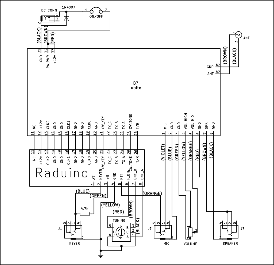
If you can follow the above, go ahead, wire it up and move on to the tune up instructions. Just remember this :
- The CW keyer has to be wired even if you don’t intend to use CW. Yes, the 4.7K resistor to 5v is a must.
- The Raduino board plugs into the µBITX board. You can unplug the LCD from the Raduino and install it separately on the front-panel with wires from the Raduino.
- Keep the wires to the antenna connector as short as you can manage.
If you need more detail instructions, read on.
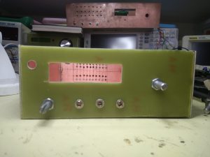
Choose a Chassis
The µBITX will work with almost any chassis, or even without a chassis! µBITX works best with an all metal chassis that has good ventilation around the heatsink.
DANGER : The heatsink of the µBITX carry the PA DC voltage. They should not be in contact with the chassis or any other metallic surface.
My personal preference is to keep the mic socket towards the edge of the front-panel so that the mic cable doesn’t get in the way of other cables and knobs. I operate the mic with my left hand and the CW key with my right hand and my transceivers line up the jacks as Mic, Headphones, Key (left to right). You may desire a different layout.
Step 1: Install all the connectors and the controls
- Install the DC connector
- Install the Antenna connector
- Install the three earphone jacks for the microphone, key and speaker
- Install the encoder
- Install the volume control
If you are left handed person, you can install the tuning encoder to the left side of the front-panel.
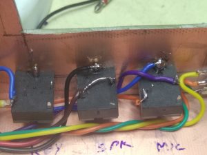
The µBITX kit comes with three 3.5mm stereo sockets. These are meant for the mic, headphones and CW key connections. The Each of these socket’s sleeve tab should be connected to the ground. This happens automatically if you are using an all metal box for this radio.
If you are using a non-metallic box, solder wires between the ground lug of each of the sockets and connect it to the DC ground. The DC ground is available on the Yellow wire connected to the encoder or at the DC socket.
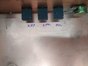
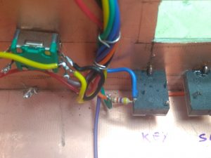
To avoid making mistakes, it is better to write the name of the socket against it, inside the chassis. See the picture below.
Step 2: Wiring up the DC connector
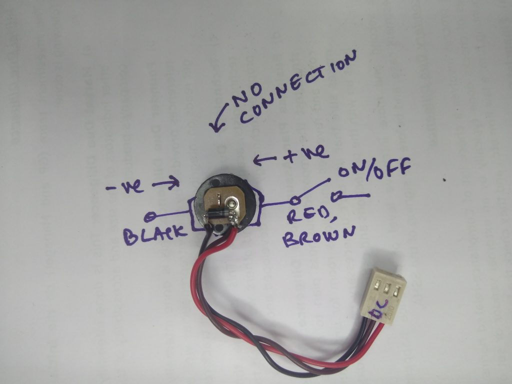
Pick up the 3-pin DC connector with cables and the 1N4007 diode (it is black in colour). Here is what the DC connector looks like from the back. 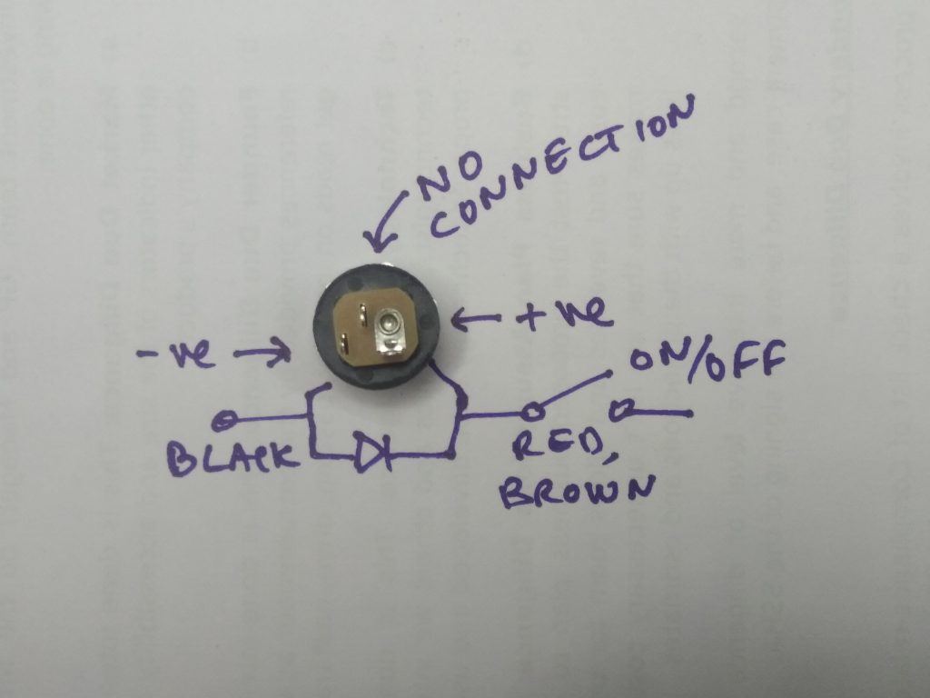
The 1N4007 has to be installed with reverse polarity. Its purpose is to conduct if you have supplied reverse voltage to the radio and burn itself out instead of the radio.
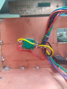
- Solder the 1N4007 diode across the DC connector. The ring of the diode should go to the positive tab of the DC connector, the other side of the diode goes to the ground tab. (See the picture below)
- Solder the DC cable’s red and brown wires together to the positive lug of the DC connector
- Solder the black wire to the ground.
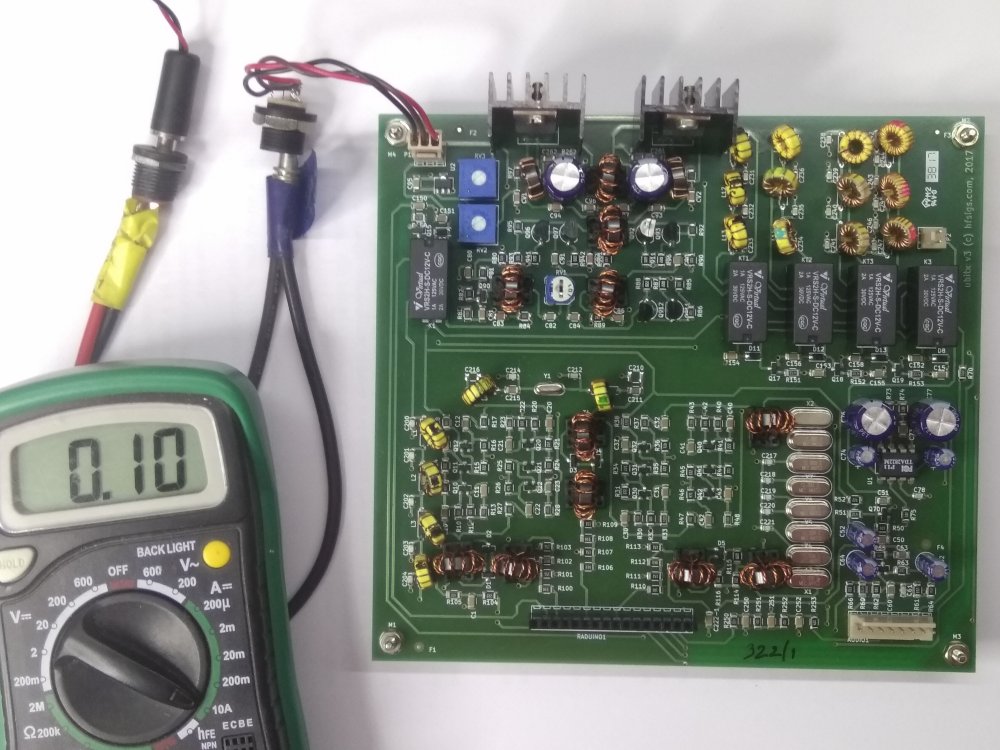
Now, plug this into the main board’s DC connector. Switch on the power and measure the current. It should be between 90ma and 110 ma.
TIP: Connect DC connector’s ground tab to chassis with a thick wire. The thick wire is needed as a a low impedance connection to the chassis prevents ground loops. This applies only if you are using a metal chassis (highly recommended).
Step 3: Prepare the Digital connector
The digital connector is an 8-bit connector that wires the Raduino board to the front panel.
Take one of the two 8-pin connectors, write ‘DIGITAL’ on top of it. Twist its wires together so that they stick together. You might want to apply some insulation tape to keep them together.
The digital connector’s wires length must be just enough to be routed to the front-panel, excess should be cut out. Leaving the wires coiled or looped around can increase the digital noise.
Step 3.1 : Wiring the up Encoder
The encoder has three tabs on one side that correspond to Encoder’s A, ground and B tabs. On the other side is the push switch. It has to be wired as follows:
- Black of the Digital connector to Encoder’s A tab (this is A0 from the Raduino board)
- Brown of the Digital connector to Encoder’s B tab (this is the A1 from the Raduino board)
- Red of the Digital connectorto Encoder’s switch (this is A2 from the Raduino board)
- Yellow of the Digital connector to Encoder’s middle tab (this is the Ground line from the Raduino board)
- The solder the remaining tab of the push switch to the digital connector’s yellow wire (it has to go to ground as well)
Step 3.2: Wiring up the PTT from the digital connector (not the mic, yet)
Connect the orange wire from the Digital connector to the mic socket’s left most tab (as seen from behind). When we wire the microphone’s line to the Audio connector, it will provide common ground for the PTT as well.
Check that the mic’s ground lug is showing connectivity with the chassis ground.
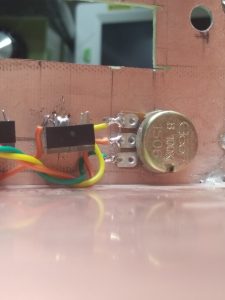
Step 3.3: Wiring up the CW Key
The CW key needs a pull-up resistor of 4.7 K from 5 volts to the key socket’s tip. The green wire from the digital connector carries 5v. The blue wire of the digital connector is the keyer line (A6 of Raduino).
- Solder the digital connector’s blue wire to the tip tab of the CW key socket
- Solder the 4.7K resistor to the CW key socket’s tip.
- Solder the digital connector’s green wire from the digital connector to the other side of the 4.7 K resistor.
DANGER : If you power up the µBITX without the pull-up resistor the µBITX can randomly go into CW transmit
Leave the violet wire (The A7). Keep it coiled. It is not used in the µBITX . If you can hack your way around the µBITX , find some use for it.
Step 4: Wiring up the Audio connector
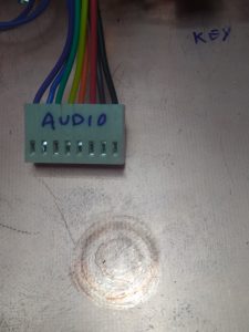
The audio connector is another 8-pin connector.
It connects to the main board of the µBITX .
It connects the mic, headphones and the volume control to the board
Write ‘Audio’ on the top of the connector to prevent swapping it with the digital connector.
Step 4.1: Wiring up the Volume Control
The green, orange and yellow wires from the Audio connector are soldered to the volume control
- Connect the green wire to the ground tab of the volume control
- Connect the yellow wire to the hot end of the volume control
- Connect the orange wire to the wiper (middle lug) of the volume control
Step 4.2: Wiring up the Microphone
The audio connector’s blue and purple wires connect to the microphone.
- The blue wire is soldered to the ground lug of the microphone socket
- The purple wire connects to the the tip of the microphone socket
Step 4.3: Wiring up the Headphones
The brown and black wires from the audio connectors carry the speaker out.
- The Brown wire is speaker output
- The Black wire is speaker ground
The brown wire has to be connected to the (both) the tip and the ring of the headphone socket.
Tip: You can connect a speaker by connecting an internal speaker to the ground lug and any of the two unconnected lugs of the headphone socket.
Step 5: Wiring up the Antenna socket
The BNC antenna socket should be mounted close to the antenna connector on the main board.
Connect the 2-pin wire connector to the antenna socket on the board. Cut the wire to the shortest length that will take it to the antenna socket.
While mounting the BNC antenna socket to the box, be sure to slip the soldering lug over the BNC socket from inside the box (between the nut and the wall of the radio box).
- Connect the black wire of the antenna connector to the lug of the BNC socket.
- Connect the brown wire of the antenna connector to the center pin of the BNC socket.
Step 6: Plugging in
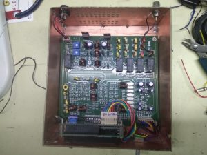
- Install the µBITX board
- Insert the Raduino board into the µBITX . Be careful, it is easy to wrongly install the board by skipping a pin.
- Connect the Audio connector to the µBITX board
- Connect the Digital connector to the Raduino board
- Connect the antenna and power connectors
Step 7: Check Out
- Plug-in a Mic (tip is Mic, ring is the PTT) and a speaker.
- Attach a low SWR antenna
- Plug-in clean 12 V DC power supply capable of at least 3 Amps.
You still, here? Go and operate!