A compact Radio Lab for Antennas, Radio circuits
The Antuino is no longer available for sale. These pages are mostly for archival purpose.
Antuino is an accurate instrument that can be used in the field to measure SWR, field strength, modulation, etc. In the lab, it can be used to sweep filters, measure gain, distortion, frequency response, etc. It works upto 150 Mhz. On the third harmonic, it is usable on 435 Mhz band as well (with reduced sensitivity).
The Antuino, unlike simpler instruments is based a superhet architecture that measures the response of the antenna or circuit at exactly the tuned frequency. It is based on Analog Devices’ Lograthmic Amplifier, the AD8307 to provide accuracy of 1db in your measurements. It is tuned with a crystal locked PLL based on Si5351 oscillator chip.
Note: The Antuino distributed at FDIM 2019 has sub-optimal performance, it can be improved by simple modifications. Read http://www.hfsignals.com/index.php/2
What can it do?
- SWR The Antuino measures the SWR of the antenna with a narrowly tuned receiver. A simpler resistive bridge with a diode detector will pick up an stray RF like local broadcast, a nearby ham radio operator or harmonics to give a false reading. The Antuino uses dual crystal filters to provide very accurate SWR at the actual frequency of measurement.
- Field Strength Meter Attach a small piece of wire (small whip) to your Antuino’s RF IN port. Now, monitor the field strength of a transmitting antenna! It allows for quick and dirty measurement of front-to-back ratios, nulls and general Apples to Oranges comparisions of different antennas.
- Cable Loss Connect the RF cable between the RF IN and RF Out ports. Set Antuino to SNA mode and set to the frequency. Read the power level.
- RF Cable velocity Connect a short piece of wire between the RF IN and RF OUT ports. Solder A length of the cable under test at the junction. Choose SNA mode and plot the frequency response. A dip will give you an accurate reading of which frequency is a quarter-wave length of the cable’s length.
- Modulation meter The Antuino can pick up signals as low as -90 dbm in power mode. A small whip antenna connected to the Antuino will allow you to monitor your own signals. Tune up and down the frequency of your transmitter to measure the splatter from distortion.
- Signal Source The RF out port of the Antuino acts as a signal source (though with square waves). You can accurately tune it to any frequency from 10 Khz to 150 Mhz.
- Frequency Response By feeding the signal from RF-OUT into a device/circuit under test and measuring the response at the RF-IN port, you can effectively measure the circuit response at any frequency. Click on PLOT to see the frequenc response.
- Plot! By clicking on the PLOT button, you can plot the frequency response of your amplifier or filter. It is a little spectrum analyzer with a tracking generator.
- Hackable The entire Antuino circuit and the software are placed under GPL license on https://github.com/afarhan/antuinov2.1
- Battery operated Power your Antuino from 6 AA cells. With the low power monochrome display, your batteries will last a long time. The current consumption is 90 mA. A set of batteries will last hours of operation. But switch it off when not in use.
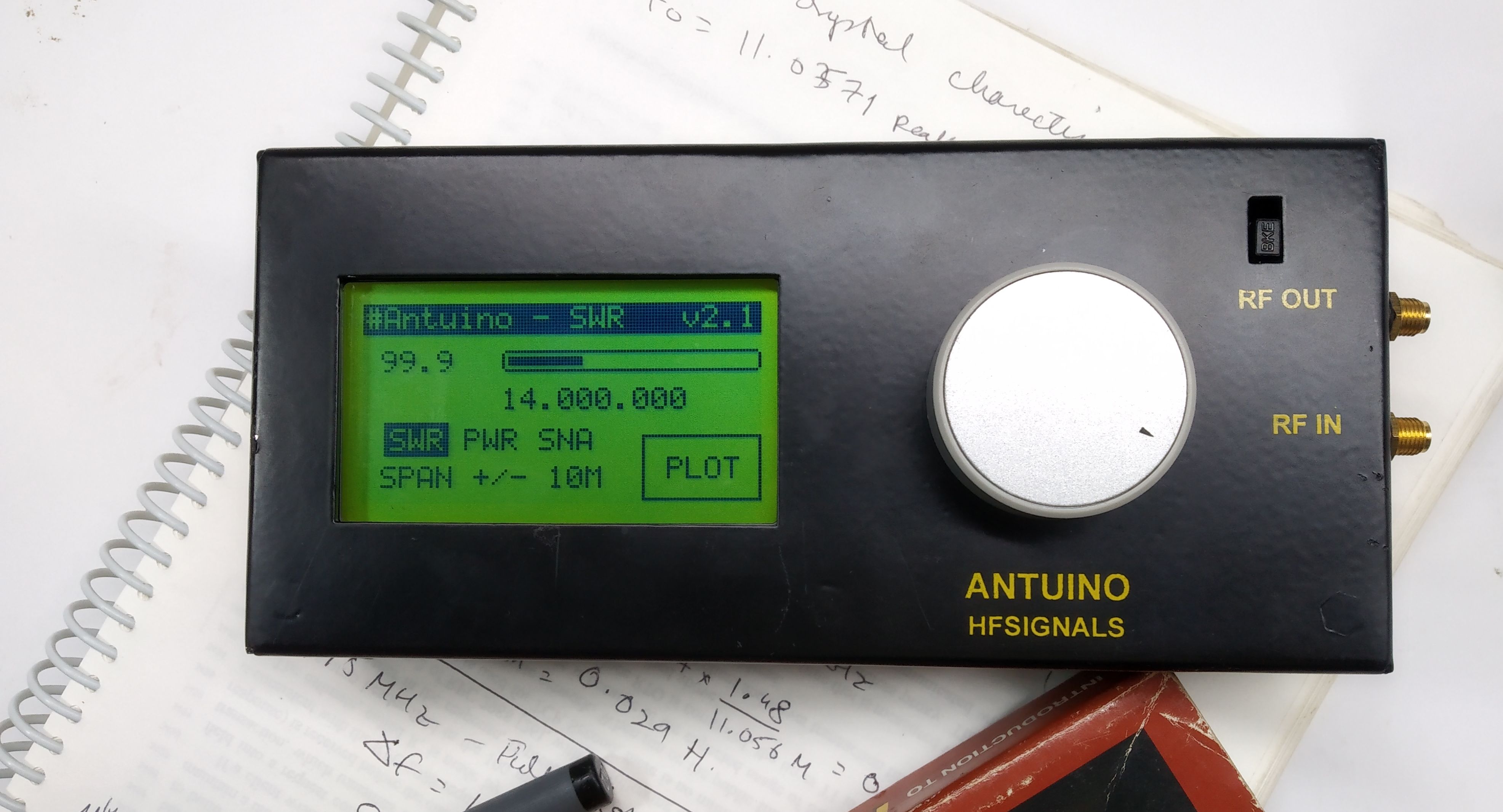
The Display 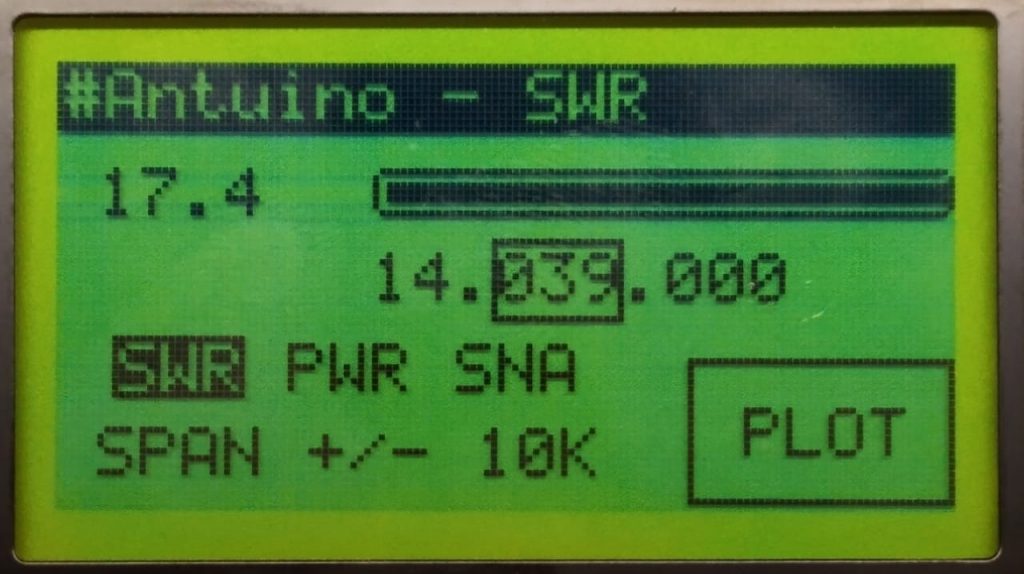
- The top line shows the current mode of operation (It is measuring SWR in the above picture).
- The second line is a meter and read-out. It is showing SWR of 17.4 as the Antuino is not connected to any antenna
- The third line shows the current frequency at which the readings are shown
- The fourth line is a choice of modes : SWR, Power meter, Scalar Network Analyzer. At the moment it is in SWR mode
- Below that is the span control where you control how large the plot is.
How to use it
There are a number of fields that can be changed. A rectangle shows which field you are on (in the picture above, we are on kilohertz field).
- To get to from one field to another you just turn the knob
- To select a field, press the knob
- To change a selected field, turn the knob to the correct value, press it again to save it.
Calibration
- Disconnect everything from both the connectors.
- Keep the encoder pressed and switch it on, this puts it in calibration mode.
- Frequency calibration – Choose Freq Calibrate from the menu and turn the knob until the RF-OUT (as monitored on a frequency counter) is exactly at 10 MHz. Press the tuning knob to save the frequency calibration.
- Return Loss Calibration – Choose Return Loss from the calibration menu. Confirm that the RF-IN port is not connected to anything. Press OK to start the return loss calibration. Wait for it to complete the calibration process.
- Switch off and switch on again.
Hacking the Software
The software is available from https://github.com/afarhan/antuinov2.1
Many have had difficulty in finding the correct GLCD library used. You can download it here