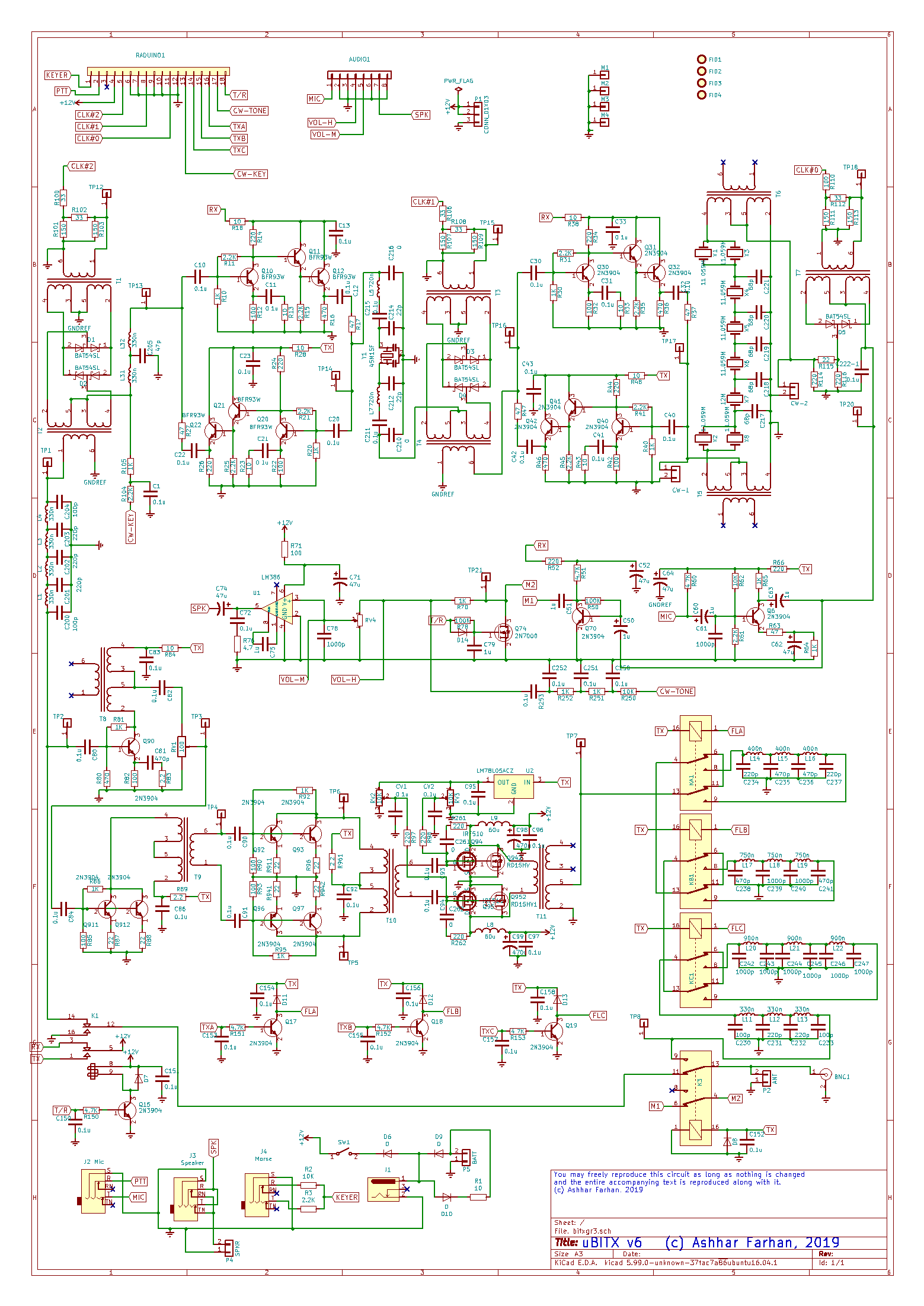
µBITX Schematic(PDF) | Raduino Circuit | µBITX ‘s Firmware
| Buy Basic Kit | Buy Full kit | Assembling the Full Kit
- Upto 10 watts pep on lower HF bands, dips to 5 watts on 28 MHz
- SSB and CW
- Simple to build and align
- Minimal controls
- Based on Arduino Nano controller and a Si5351 for all local oscillators
- Double conversion, superhet architecture
- It can be scratch built for less than $50 or you can just buy the kit
Note: Looking for circuit description of earlier versions of uBITX?
Click here for (v3) uBITX | (v4) uBITX | v5 uBITX
Homebrewers have traditionally avoided making multiband transceivers as they can get extremely complex and difficult to make. There have been some remarkable successes in the past, the CDG2000 (designed by Colin Horrabin G3SBI, Dave Roberts G8KBB and George Fare G3OGQ) is one such design. The Software Defined Radio (SDR) route as followed by several designs offer some simplification at the cost of bringing digital signal processing and a PC into the signal path.
On the other hand, many of the homebrewers do need a general coverage transceiver on the bench as well as as a base transceiver for bands beyond the HF. I ended up buying an FT-817ND that has been a reliable old warhorse for years. A few years ago, I attempted a high performance, multi-band architecture with the Minima transceiver. The KISS mixer of the Minima, though a very respectable receiver front-end, had serious leakage of the local oscillator that caused that design to be abandoned as a full transceiver. Over months, I realized that the need for a general coverage HF transceiver was wide-spread among the homebrewers. Most of us simply end up buying one.
While achieving competition-grade performance from a multiband homebrew transceiver is a complex task, as evidenced by the works like that of HBR2000 by VE7CA, it is not at all difficult to achieve a more modest design goal with far lesser complexity. The µBITX aims to fulfill such a need. It is a compact, single board design that covers the entire HF range with a few minor trade-offs. This rig has been in regular use on forty and twenty meters for a year at VU2ESE. It satisfies for regular work, a few trips to the field as well.
A key challenge for multiband transceivers has been to realize a local oscillator system with such wide range. Silicon Labs has now produced a series of well-performing oscillators that solve this challenge trivially : You connect the oscillator chip over a pair of I2C lines and it is done. The Si5351a/b/c are one such a family of parts that provides 3 programmable oscillator outputs in a small 10 pin TSSOP package. We exploit this chip to build the multiband transceiver.
Having exclusively used homebrew transceivers all the time, I get very confused whenever I need to use a commercial radio. There are too many switches, modes and knobs to twirl around. The µBITX use an Arduino to simplify the front panel while retaining all the functionality in a simple menu system that works with the tuning knob and a single function button. The rig supports two VFOs, RIT, calibration, CW semi break-in, meter indicator, etc. In future, more software can be added to implement keyer, SWR display, etc.
The Circuit Description
A contemporary approach to multiband superhet radio is to upconvert the entire spectrum of interest (0.5 to 30 Mhz) to much higher intermediate frequency that is at least 1-½ times the highest frequency of interest (for us that would be 45 MHz). Though narrow band SSB filters are available at 45 MHz, they are do not have a good response in addition to being costly and difficult to obtain. Hence, we choose to an inexpensive, though 15 KHz wide, 2 pole 45 MHz filter as a roofing filter. This filter sets the wide-range IMD of the receiver.
To tune from 0 to 30 MHz, the first oscillator tunes from 45 MHz to 75 Mhz. Accordingly, the IF images will be from 90 MHz to 125 MHz. These are easily stripped away by a 4-section, low pass filter in the front-end. A higher first Intermediate Frequency could have resulted in even better image rejection.
The second IF of 11.059 MHz allows for a very reasonable SSB bandwidth filter. We use 8 well-matched low cost crystals to obtain a very smooth filter. Some CW operators may also want to add a second narrow band filter for CW work, more on this when we discuss the CW mode.
Here is the block diagram of the µBITX :
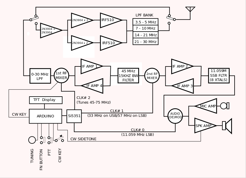
Low Pass filter at 30 MHz
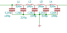
The receiver front-end has a 0-30 MHz filter low pass filter (shown as the left-most block in the diagram above). This is a simple four-section filter that was interestingly described by Wes Hayward on his own website, (the original article that had very useful information about building filters on pcbs. It is, sadly, no longer available). The four sections of low pass filtering has adequate attenuation at 90 MHz and beyond.
1st Conversion
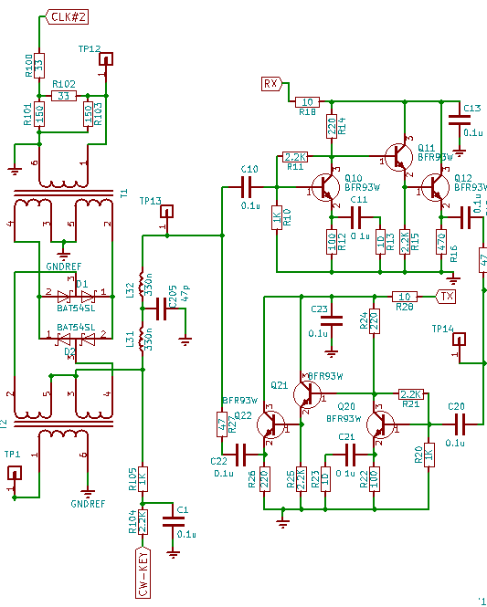
The receiver front-end has a doubly-balanced diode mixer without a preamplifier. A preamp would have been necessary if the front-end had a higher loss band pass filters. The low pass filter has a loss of about 1 db, eliminating the need for a preamp to follow it. The diode mixer’s loss is another 7 db. The overall noise figure is probably about 13db. A 0.1uv signal is clearly audible.
The diode mixer is a standard issue doubly-balanced mixer. Versions built with 1N4148 as well as BAT54S (a very inexpensive, useful part that has two matched diodes in a single SMD package) work equally well.
The [CW_KEY] label in the above circuit provides CW operation. We will discuss this later in this article.
You should know about the front-end mixer :
- The L31, C205, L32 together form a single low pass filter that attenuates the 2nd harmonic of 45 MHz from getting into the diode mixer (during the transmit state). This cures the spurs that were reported in earlier versions.
- A preamp would have been necessary if the front-end had a higher loss band pass filters.
- The low pass filter has a loss of about 1 db, eliminating the need for a preamp to follow it.
- The diode mixer is a standard issue doubly balanced mixer. Version built with 1N4148 as well as BAT54S (a very inexpensive, useful part that has two matched diodes in a single SMD package) work equally well. The diode mixer has a DC bias that can be raised to unbalance it and allow CW operation (more about it later)
- The mixer is fed from clock#2 of the Si5351 through an attenuation pad. The pad provides proper termination to the Si5351 and a proper drive to the diode mixers.
The diode mixers need an SWR of 1:1 at all the three ports (RF, IF and the oscillator drive). Improper matching of the diode mixers can lead to a large number of spurious responses.
For those building the µBITX from scratch, remember that the leads from the Si5351 to this mixer should be kept very short. Longer leads will result in picking up of clock #1 signals from the Si5351 which can create transmit spurs that are 11 Mhz away from the carrier frequency.
The mixer is followed by a post-mixer amplifier (labelled RX 1st AMP). We used the excellent termination insensitive amplifiers (TIA) developed by Wes Hayward and Bob Kopski (read about them on www.w7zoi.net). These amplifiers work without transformers and they provide excellent termination on both sides. This is a key requirement for bidirectional transceivers like the µBITX . We use four blocks of these amplifiers in this transceiver. The amplifier block has a gain of 16 db and OIP3 of about +20 dbm as measured inside the µBITX .
This amplifier does three important things at once :
- it provides necessary gain to overcome the losses in the following 45 MHz band pass filter,
- it provides proper broadband termination to the mixer at all HF frequencies,
- it provides proper driving impedance for the 45 MHz band pass filter.
45 MHz Band Pass Filter
A low cost two-pole 45 MHz crystal filters are now widely available from online sources. We used this to eliminate the guess work with tuning a band pass filter and also to provide better selectivity early in the transceiver’s signal path.
The 45 MHz filter needs 500 ohms termination impedance on both ports. We use simple L network to match the filter to either ends of the front-end and the 2nd IF mixer.
Note: We had use a series tuned, three section band pass filter at 45 MHz for the prototype. This filter was been purposefully kept a little broad to eliminate the need to tune it. Experimentally inclined scratch-builders may choose to use air core coils with proper shielding for this stage.
2nd Conversion
The second RF mixer down converts the 45 MHz IF to 11.059 MHz. Earlier versions had the second IF at 12 Mhz, this is moved to 11.059 MHz to avoid spurs from the microcontroller. It uses another standard issue double-balanced diode mixer followed by another clone of the RF amplifier used in the front-end. To invert the sideband between USB and LSB, the second oscillator is switched between 33 MHz and 57 MHz. This is controlled by the µBITX software.
11.059 MHz SSB filter
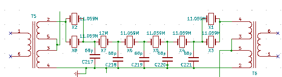
The ladder topology is now enhanced with the improvisation suggested by G3UUR. Paralleling up crystals at two ends of the regular ladder filter of Cohn topology really flattens out the response and even improves the losses. We use a six-section ladder filter here as we can afford the slightly higher losses given that we have had enough gain from the preceding stages.
Microprocessor-grade crystals are available cheaply and are well suited for the purpose. The lower Q of these crystals results in higher losses. We can handle the higher losses by increasing the gain in the 2nd RF amps that in turn results in slightly lower IIP3 (it is about +5 dbm as measured) at close range.
The 11 MHz filter needs 200 ohms termination at both ends. We achieve this through 1:4 transformers that have the robust 50 ohms terminations. Taking care to terminate filters properly is the secret to having a nice sounding radio.
(De)Modulator
The post filter signal is strong enough to not need an IF amplifier, so we directly take it to a balanced (de)modulator made out of two matched diodes. It is important to use matched diodes here as the same circuit is also used to modulate during transmission.
Balance controls are pesky circuits, they are easily unbalanced and setting them properly is more difficult than finding two diodes with the same forward resistance and soldering in the pair. An easier option it to just order a small strip of the inexpensive BAT54S which come as pre-matched pair for a few pennies each.
We use the remaining CLK#0 output of the Si5351 to drive the BFO. The carrier is permanently fixed to generate upper sideband signal. The sideband is inverted by flipping the second oscillator between 33 MHz and 56 MHz. When the second oscillator is at 34 MHz, the upper sideband propagates either way without inversion as 33 + 11 = 45 MHz. When the second oscillator is at 56 MHz, the 45 MHz is generated as 56-11 = 45 MHz. Note that in the second case, the 45 MHz signal will decrease in frequency as the 11 MHz signal is subtracted from 56 MHz, thus achieving sideband inversion. A few minutes of pencil and paper work will be required to figure out how this works.
Audio
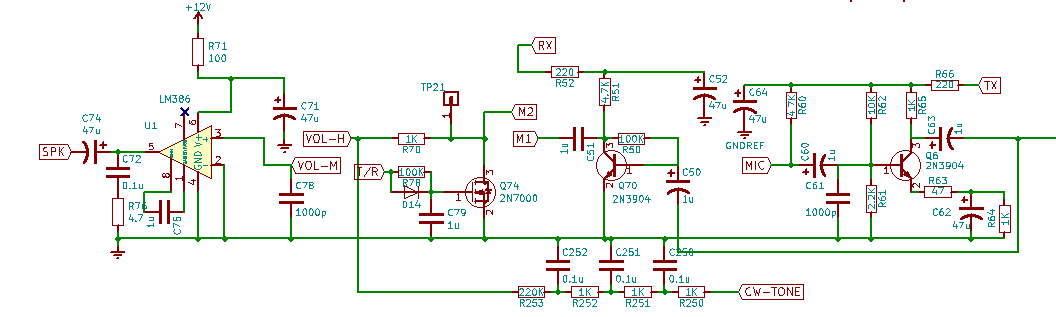
The audio preamp is a carry over from the microR1 direct conversion receiver’s simple audio amp. This must be the simplest circuit block in the radio, yet it has the most gain in the entire receiver chain. Using fewer active devices in the amplifier chain is really the key to low distortion audio. This is supported by Math.
The audio amplifier in the updated (revision 5 onwards) uses the LM386. It can drive a small speaker. If you prefer headphone operations over speaker, you may remove the 1uf capacitor between pins 1 and 8 for lower distortion. You may, if required, substitute this for any other audio amplifier of your choice.
A 2N7000 is used to mute the audio from the signal path while transmitting. It prevents thump of the T/R circuitry from getting into the speaker output.
CW sidetone
The CW sidetone is generated as a square wave from the Arduino. It passes through an RC low pass filter to the audio amp during key down periods
Transmitting
The transmission is really the same signal flow in the reverse direction. The mic has a bias resistor to allow for electret microphones. The output at the low pass filter is about -10dbm. The transmit power chain has a two 2N3904 broad band class A amps that boost the power to about +13 dbm level.
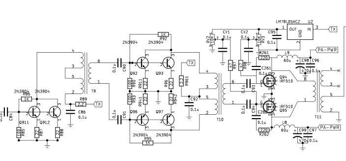
The power chain uses four common plastic 2N3904s in push-pull as drivers. The 2N3904s have enough gain at 30 MHz. The 2N2219s tried earlier were found to have low gain at higher frequencies.
Two IRF510s are used in push-pulll. The IRF510s are a favorite among the homebrewers and they are low cost – an important consideration if you accidentally blow them up.
The push-pull amps cancel the even order harmonics significantly. Four harmonic filters are sufficient to provide more than 43 db of required suppression of spurious outputs.
Software Description
The Arduino source code for the µBITX is available on https://github.com/afarhan/ubitxv6
The Arduino works with a common 320×240 TFT display using the ILI9341 display controller and an Si5351A. The software controls the oscillator, implements two VFOs, and provides a calibration routine. The code is always changing so it may do things not mentioned here.
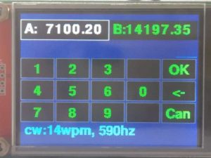
Operating the Radio
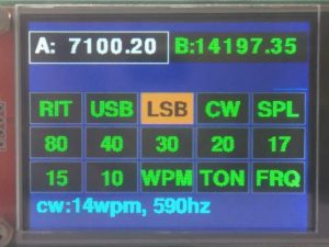
- VFOs The VFOs A and B are switch by simply touching on either of them. The white box shows the currently active VFO
- RIT Touch the RIT to enable Receiver Incremental Tuning. Touch it again to turn it off
- USB/LSB Touch on either of the buttons to choose the sideband
- CW Touch to enable CW mode. In CW mode, you can also use your microphone’s PTT for a transmitting a quick morse code message. Choose your keyer from the setup menu
- SPL(IT). Touch to enable Split operating. Now, the VFO A becomes the transmitting frequency and the VFO B is the receiving frequency. It is great for working DX!
- Bands Touch on any band buttons to quickly switch to the band
- WPM (CW) Set the CW sending speed of the keyer
- TON(E) Set the sidetone frequency
- FRQ Allows you to enter a frequency directly using a keypad shown below:
Shortcuts
The ubitx v6 has a few shortcuts:
- If you tap on the tuning control, you can move the focus on the screen from one box to another. Tapping the tuning control again will simulate pressing that button.
- If you tap on one of the VFOs, Fast tuning gets enabled where each step of the tuning encoder results in a jump of 50 KHz. Use this method for quickly getting from one frequency to another.
- The radio switches automatically to LSB when operating below 10 MHz.
- To operate CW, the setup menu allows you to chose between Iambic A, Iambic B and a straight (hand) key.
CW Mode
With the fading sunspots, many of our radio compadres are rediscovering the joys of primitive CW where a good ear, a modest dipole and 10 watts still gets you decent DX. The µBITX center stages the CW operation. A personal preference to use wider bandwidth has resulted in a single filter for SSB as well as CW, there is no reason why a line from Arduino cannot be used to switch to a narrower 500 Hz filter for CW.
Given that the BFO is completely progammable, there is little need for the CW filter to also be at 11.059 MHz, For instance a 5 MHz IF maybe more suitable for a narrow CW filter.
The CW is generated like this:
- The second oscillator and the BFO as disabled
- The first oscillator is moved to the actual transmit frequency
- A DC bias is fed to the first mixer to upset the balance and allow the first oscillator to leak to the RF power chain.
- The CW sidetone is generated from the Arduino and injected into the audio amplifier

 Design Notes
Though a double conversion superhet, this design is scarcely more elaborate than its forerunner, the original BITX20. The original BITX20 had three stages of amplification, this has just two. The original BITX20 used two oscillators, this design uses a single Si5351A (the size of a transistor) to generate three frequencies. Technology has dramatically evolved in the last decade. Newer devices, newer platforms, like the Arduino, have put a lot of power and flexibility in the hands of the homebrewer. This design is a testimony to that.
Double conversion radios are considered a complex beast. However, with judicious choice of frequencies and careful distribution of gain, it is possible to get quite satisfactory performance that is just a few decibels below that of a narrow band single conversion superhet. Extensive amount of mental homebrewing with cascade.exe supplied on the EMRFD’s accompanying CD resulted in the current topology. A surprise discovery was that it was wholly unnecessary to add IF amplification after the SSB filter!
The filters were extensively simulated on the software that accompanies the book Experimental Methods in RF Design. The LADBUILD was used to build the filters and the GPLA was used to run the simulations. The transmit filters were simulated on LTSpice. A Rigol DSA815 spectrum analyzer was used to ascertain the filters’ performance.
The entire transceiver, minus the digital board containing the Arduino, Si5351 and the display, is built on a small 6.5″ by 6.5″ copper clad, double sided board. SMD 1206 size components are used extensively them. Except for the Audio power amp, the large value electrolytics and the transmit power chain, SMDs were used everywhere.
The main board has an all the connectors pre-soldered.
The digital board, also known as TFT Raduino, is a general purpose Arduino board with the Si5351a and the 320×240, large TFT colour display of 2.8 inches. It has a bottom connector that brings out the three clocks and a few digital pins. This connector mounts on the main board with an 18 pin, L-shaped connector.
Another 6 pin connector on the TFT Raduino board connects to the tuning encoder on the front-panel.
There are several places where the layout is critical:
- The bandpass filter and the low pass filter are kept at right angles to each other to reduce coupling
- The Si5351a clocks should have very short leads going to their respective mixers and they should be away each other as well as from any power leads to prevent leakage of their RF into the transmit path.
- The transmit low pass filters are mount as way from the low pass filters as possible.
One could relax these constraints if one used better shielding.
Coil Details
- L5, L7 : 12 turns on T30-6
- L1, L2, L3, L4, L11, L12, L13 : 9 turns on T30-6
- L14, L15, L16: 10 turns on T30-6
- L14, L15, L16: 14 turns on T30-6
- L20, L21, L22: 19 turns on T30-6
All the RF transfomers are 8-10 trifilar turns on FT37-43
Improvements
- Broadcast filter If there are powerful Medium wave or LF transmitters in the immediate vicinity of your QTH, it will make sense to add a high pass filter with a cut-off around 1.6 MHz to keep these out of the front-end.
- Better IF system An IF derived AGC with sufficient gain control, a selection of another narrow band filter can easily add a lot of street cred to this little radio. The hybrid cascode amplifier described by Hayward and Damm is highly recommended.
- VHF/UHF coverage With the 45 MHz IF, it is trivial to build band-pass filters with microstriplines for 144 MHz, 220 MHz and 432 Mhz frequencies. The Si5351’s clock may not high enough for the first conversion directly at 432 Mhz but a sub-harmonic mixer that works with only half the local oscillator frequency can easily scale this rig for VHF/UHF work. MMICs like the MAR6 series and power modules from Mitsubishi can easily scale this radio to reasonable performance level for weak signal and satellite work.
After thoughts
As a fresh radio amateur in the 80s, one looked at the complex multiband radios of the day with awe. I remember seeing the Atlas 210x, the Icom 720 and Signal One radios in various friends’ shacks. It was entirely out of one’s realm to imagine building such a general coverage transceiver in the home lab.
Devices are now available readily across the globe through online stores, manufacturers are more forthcoming with their data. Most importantly, online communties like the EMRFD’s Yahoo group, the QRP LABS and BITX20’s groups.io community etc have placed the tribal knowledge within the grasp of far flung builders like I am.
One knows that it was just a matter of breaking down everything into amplifiers, filters, mixers and oscillators, but that is just theory. The practice of bringing a radio to life is a perpetual ambition. The first signal that the sputters through ether, past your mess of wires into your ears and the first signal that leaps out into the space from your hand is stuff of subliminal beauty that is the rare preserve of the homebrewer alone.
At a recent eyeball meet, our late friend Dev(VU2DEV, SK) the famous homebrewer said “Now is the best time to be a homebrewer”. I couldn’t disagree.