This is a quick guide to assembling the sBitx. Although it is meant for assembling the sBitx boards into the HF Signals enclosure, it can also be used as a guide for those putting together their own sBitx from the boards.
Step 1: Preparing the Digital Card
1. Carefully unlatch the tiny black side-clamps from either side of the DSI connector of the Raspberry Pi. Be careful as the black clamps can easily dislodge from the connector, they should just become unlatched not dislodged.
2. Insert the display connector ribbon, with the blue strip towards the edge of the board,into the Raspberry Pi’s DSI port firmly until the silver edge. It should sit inside properly. Now, click the side clamps back in place.
3. Insert the SD card. The SD card’s gold plated contacts should be facing the board.
4. Install the four M2.5 standoffs on the four mounting holes of the Raspberry Pi with the M2.5 screws. Do not use M3 screws for this ! (M3 screws are for mounting the main board into the encloure)
Step 2: Installing the main board into enclosure
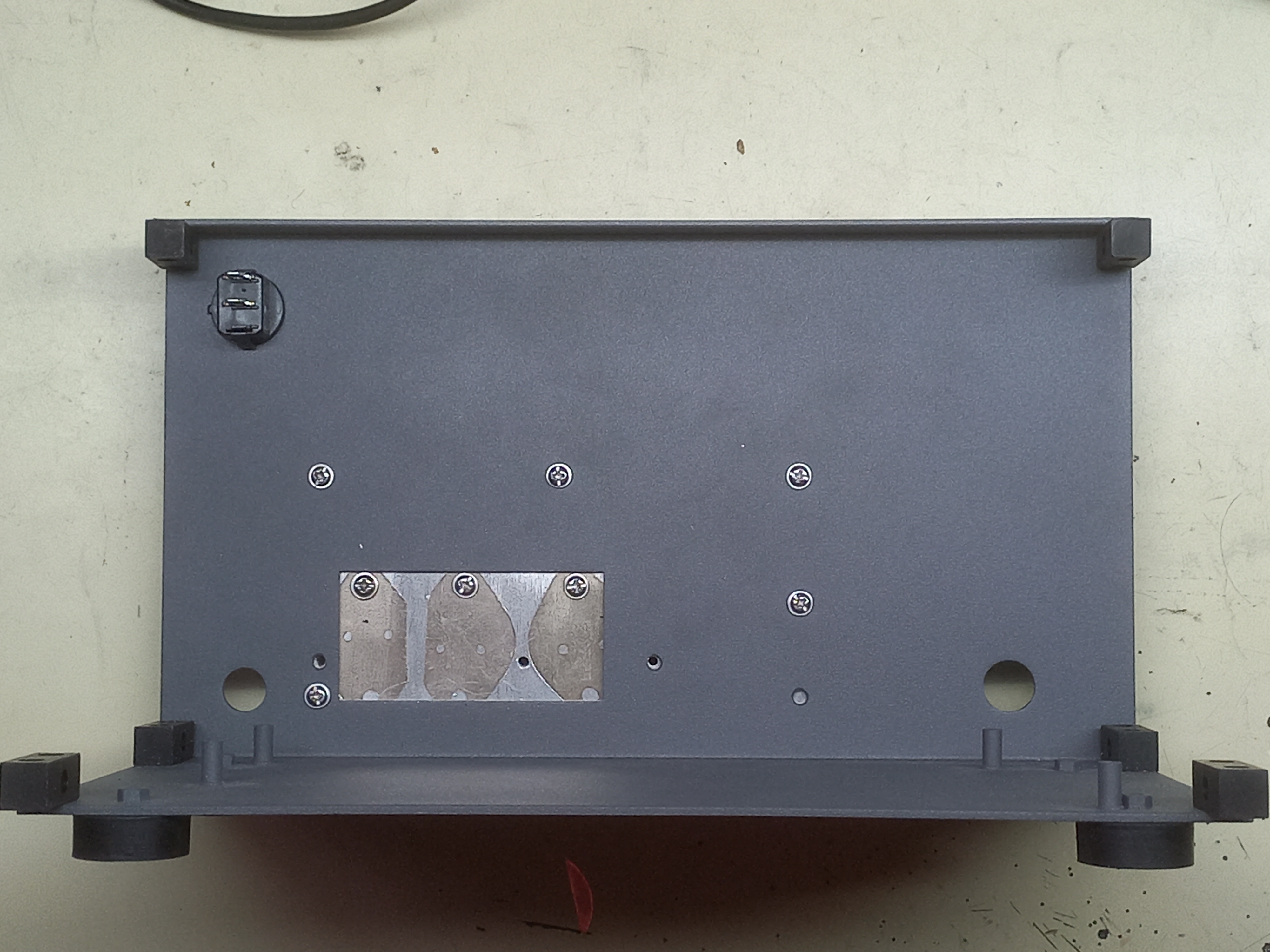
1. Fix the back panel to the bottom panel with the M5 screws using two of the corner blocks.
2. Install the heatsink with five M3 screws. There are additional holes but we use only five to install the heatsink. It should now look like below:
3. Insert the mainboard and secure it with four M3 screws to the base plate.
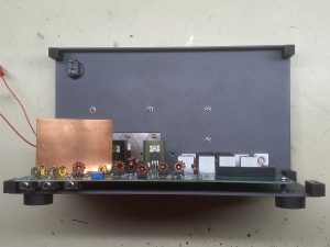
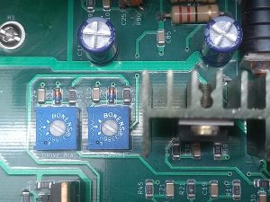
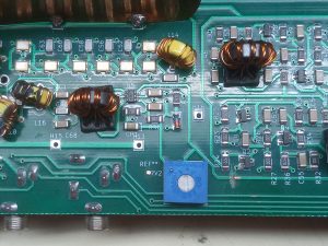
4. Turn the DRIVE_BIAS and PA_BIAS fully counter-clockwise. Set the RV2 to middle position.
5. Install the heatsink clamp across the three TO-220 devices with the three long M3 screws. Don’t tigthen at all. Just screw the three in so that the clamp is still loose. Insert the small silicon-rubber heatsink pad between the clamp and the middle device.
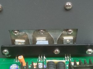
6. You may have to bend the copper shield a little to get to the left most screw.
7. Now tighten each of the clamp screws one by one until all of them show some resistance. Don’t overtigthen them as that can lead to stress when the transistors get home. If they are loose then the heat build up will blow them up.
8. Connect the red switch wires to the power switch on the back panel. Either of the wires can be connected to the switch lugs.
9. Connect a 12VDC to 13.8V DC power supply and switch on the mainboard from the back switch. It should consume between 90mA and 120 ma of power.
10. Switch off the power and disconnect the power supply.
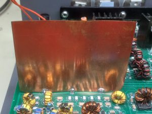
11. Check that the copper shield is still soldered properly. If not, resolder it back.
10. Install the left panel with 3 M5 screws to the corner block. Note that the air vents of the left panel should be towards the back of the enclosure.
Preparing the Front Panel
1. Install the display back plate to the front panel with four M3 screws.
2. Insert the display from the front until the display mounting holes match up with back plate holes. Pull out the brown and black display power cord through the center cutout of the back plate.
3. Install the four counter-sunk M3 screws to mount the display to the front-panel.
4. Insert the 10-pin encoder cable into the encoder board.
5. Install the encoder board to the front panel and secure it with encoder nuts. Don’t overtighten the nuts as it can damage the encoder.
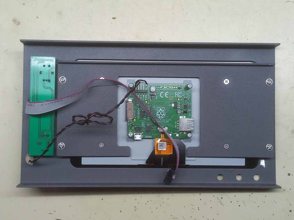
6. Insert the tuning knob and the function knobs over the encoders. Secure them to the encoders by tigthening the screw with a small flat-head screwdriver.
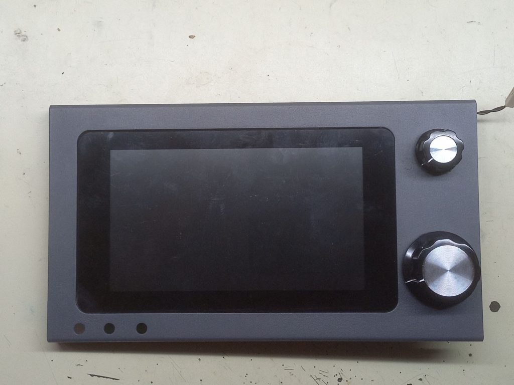
Installing the front-panel
1. Slip the front-panel onto the base, take care to not damage the three jacks that come out from the main board. Secure it with two M5 screws in the bottom and one on the top left.
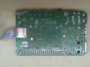
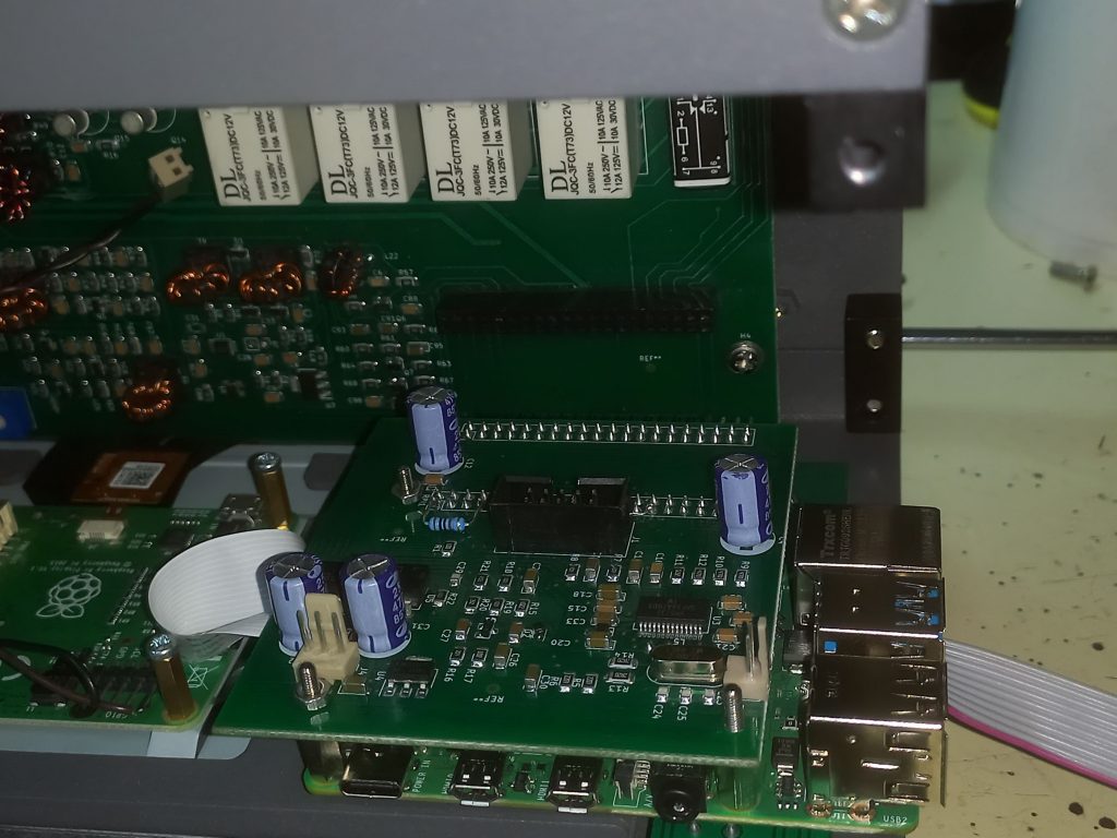
Installing the Digital Board
This needs extreme care. If you install it improperly, you can damage both boards instantenously.
1. Lie the radio with the front-panel facing down.
2. Place the digital board with raspberry pi up, the connector facing out next to the display.
3. Gently snap-off the side clamps of the display’s DSI connector and insert the display ribbon connector cable into the display. The silver coloured edge should be facing up as it is inserted into the connector. Now snap the clamp back on. Gently pull back the ribbon to check that the ribbon is properly installed.
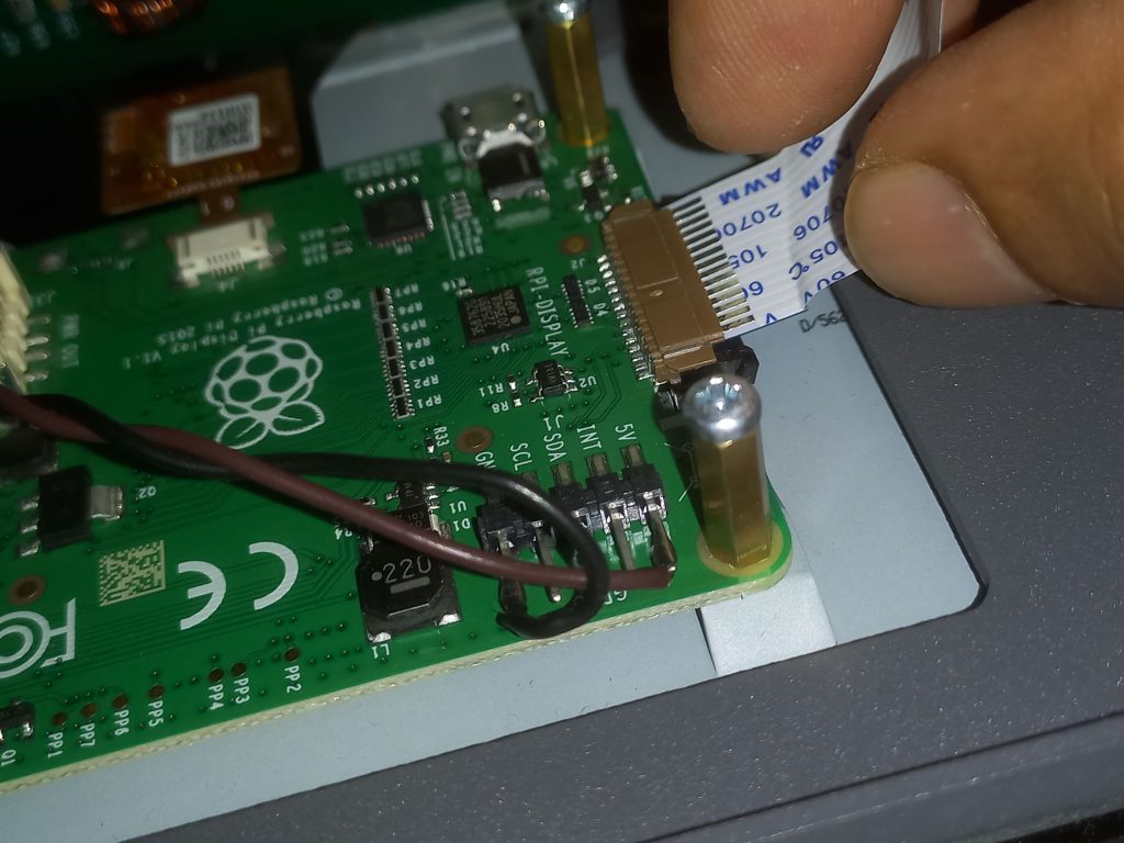
4. Carefully, making sure not to pull on the display ribbon cable, turn the raspberry pi around so that the digital board is up (facing you) and the raspberry pi is below (facing the front-panel)
5. Now insert the digital board into the 40 pin connector on the main board.
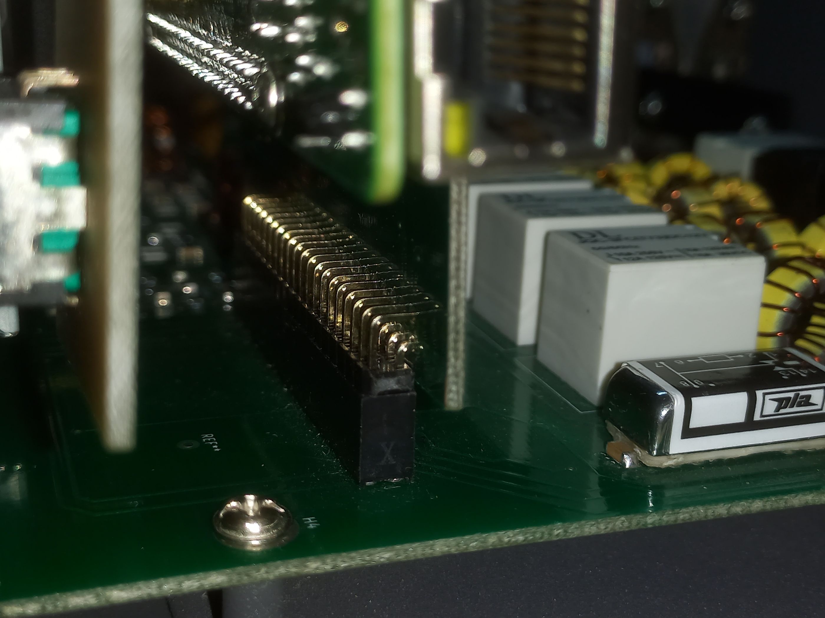
6. Very important, check that all the 40 header pins of the digital board are inserted properly. It is easy to insert it such that either 20 pins of one row are outside the connector or that one or two pins have slipped to the side.
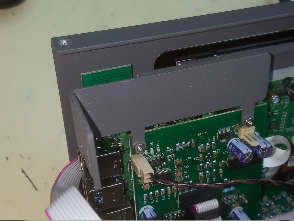
7. Slip the L-bracket support onto the digital board’s top two M2.5 screws and install the nuts over them.
8. Connect the display power cable to the 2 pin connector on the display board.
9. Connect the 10 pin encoder cable from the front-panel to the display board.
10. Check out the that radio is properly powering on by connecting the power supply and switching it on. Wait until the main display is showing before switching it off.
Closing the Enclosure
1. Mount the right side plate with 4 x M5 screws. Ensure that the right side plate’s screws for mounting the L-bracket are inserted properly inside their slot. Fasten the L-bracket to the right panel with two M3 screws.
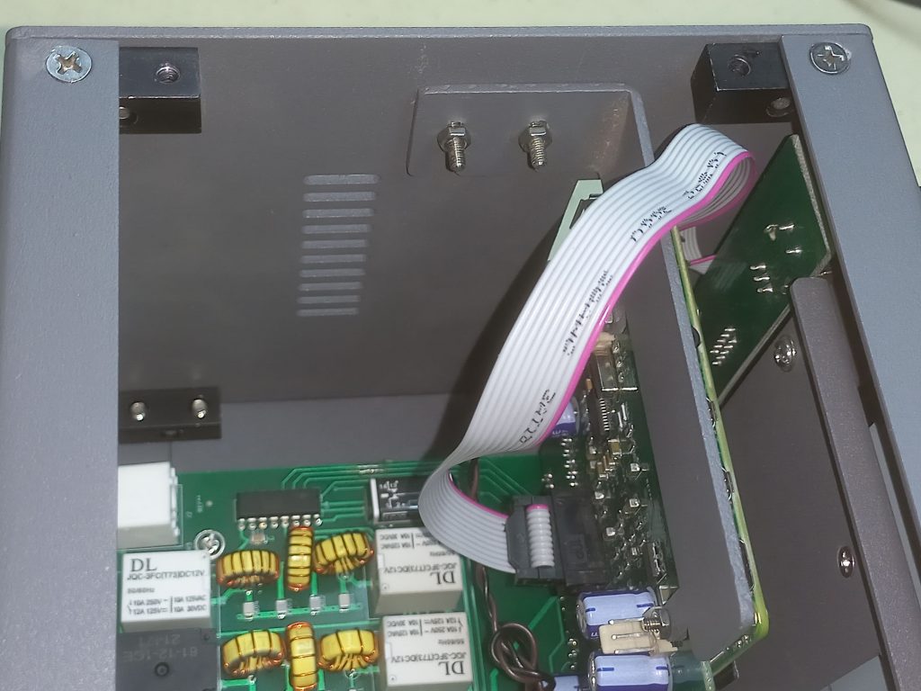
2. Take the top panel, insert the speaker cable into the 3-pin connector on the digital board. Fasten the top-panel with four M5 screws.
Initial Setup
- Attach a 13.8V, 10 A power supply, a dummy load to the sBitx and a microphone (The microphone connector is the left most on the front-panel).
- Switch on the sBitx and note the current draw (it should be under 1.5A if you are using the LM338 regulator, if you have upgraded to a switching regulator it should be under 0.6A)
- Start the sBitx software by clicking on the Icon.
- Select Mode as USB. Reduce the MIC to zero.
- Press the PTT.
- Without speaking into the microphone, carefully increase the DRIVE_BIAS POT until the current increases by 200 mA. Note the current.
- Keeping the PTT on the microphone pressed, now increase the PA_BIAS POT until the current increases by another 200 mA.
- Release the PTT.
The sBitx should be now ready to use, Happy DX!