The Dayton Antuino has sub-optimal performance. This is a short note on improving it to an 80 db range of measurements. The trouble with Antuino 2.0 (the one distributed at FDIM/Dayton 2019) is that it had too much gain and the IF amplifiers didn’t have enough juice to handle high level signals. There were a few quirks in the software as well. We have sorted them out.
To upgrade, you will need to do (1) Software Upgrade, (2) Hardware Modifications and (3) Calibration
Software Upgrade
First, you must download the latest files from https://github.com/afarhan/antuinov2.1. Upload these to the Antuino using the Arduino IDE. See some online videos to learn how to do it. It is quite simple, really.
Hardware Modifications
Here is the updated circuit with the changes marked out (in addition to replacing Q1, Q2 with 2N3904s.
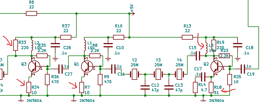
First, we have to replace the of Q1 and Q3 with 2nN3904s. The V2 had BFR93W transistors that had too much gain. You can choose to solder the leaded ones if you do not have the SMT version.
Second, we have to increase the standing current in all the three amplifier stages. We do this in the following way:
- Remove R32 (not shown in the circuit diagram above as it is removed)
- Remove R4 (not shown in the circuit diagram above as it is removed)
- Change R34 from 100 ohms to 10 ohms
- Change R7 from 100 ohms to 10 ohms
- Change R18 from 100 ohms to 51 ohms
- Add approximately 10 uh inductor in parallel to R19 (220 ohms). We use 10 turns on FT37-43 toroid.
- Replace Q1 (BFR93W) with 2N3904
- Replace Q2 (BFR93W) with 2N3904
- Replace R33 (51 ohms) with 220 ohms
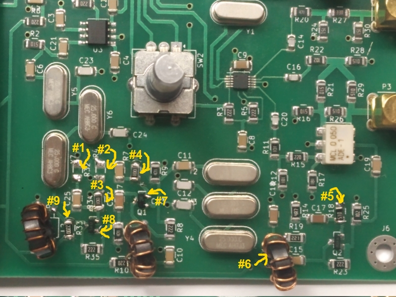
Here is the a picture of a modded V2 PCB.
Calibration
- Switch off the unit, remove the USB cable if any.
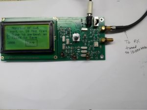
- Connect the RF Out connector (the upper one) to an accurate 10 MHz frequency counter or a receiver tuned to 10 MHz
- Keeping the Knob pressed, switch on the unit. Release after 2 seconds. (Note that while the knob is pressed, the display is off, it turns on only when you release it)
- The calibration menu will appear
- Choose Freq Calibrate. Tune the Antuino until the RF Out signal is exactly at 10 MHz, click to save, this returns you back to the Main calbrate menu.
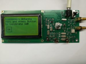
- Choose Return Loss. Check that nothing is connected on RF In connector. Press OK to begin calibration. It will return to the Main calilbration menu onces done.
- Switch off the unit and switch it on again to resume regular operation.