- The brown wire from Raduino goes to the black wire from the BITX DDS
- The red wire from Raduino goes to the brown wire from the BITX DDS
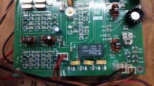
- The BNC antenna connector must be not more than 2 inches way from the antenna connector on the board
- The box should have enough head room to allow the heatsink. The heatsink is not at ground potential. It should’nt touch any metal
- Use a well regulated 12 volts, 2 amps linear power supply for best performance
- Keep all the leads short
Below is the connection diagram.
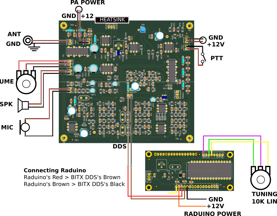
 This diagram is all you need to know to hook you your BITX40. You may want to follow the steps below to hook it up.
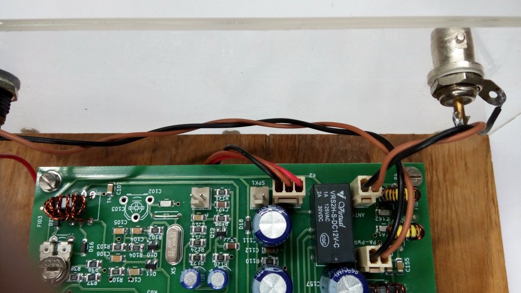
Step 1: The Antenna Connector
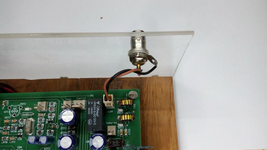

- Mount the board and the BNC antenna connector close to each other
- Mount the BNC connector on the transceiver box with the ground lug
- Use a 2 pin connector between the antenna connector on the board and the BNC connector
- The Black wire goes to the ground lug of the BNC, the brown to the central conductor
- Keep the antenna wire to be less than 3 inches
Step 2: DC Power Connections
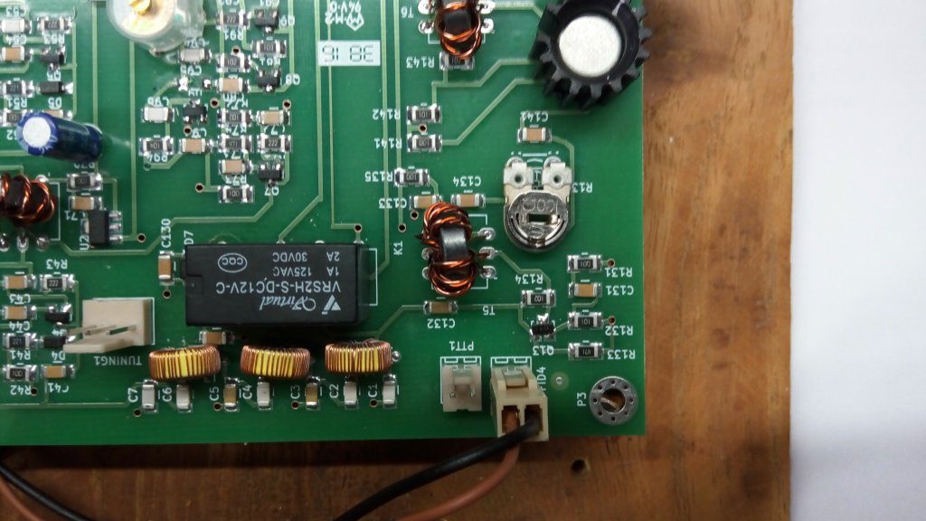
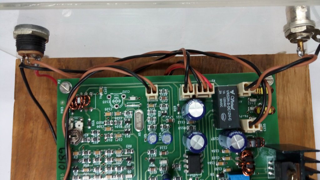
The DC power from the socket goes to the board through the on/off switch on the volume control. From the ON/OFF switch, route the power a parallel connection also goes to the transmitter power amplifier. This is kept as a separate connection on the board so that you can feed the power amp with a higher voltage.
- Use a two-wire connector as shown in the diagram’s upper right side to supply +12v power to the board.

- The brown wire should go to +12V line from the power supply and the black wire should go to ground line of the power supply.
- The supplied DC socket can be hooked to the DC power lines. The large pin on the DC socket is the postive line (see the picture below
- You may route the positive power line through the ON/OFF switch on the volume control
- Use another PA POWER line to feed power to the Power Amplifier. This is shown on the top-left part of the wiring diagram

Step 3: Wireup the Raduino
Take the LCD display apart from the Raduino and mount it on the front-panel. Now, plug-in the Raduino behind it. Carefully note that all the 16 pins of the display are properly slipped into the Raduino connector.
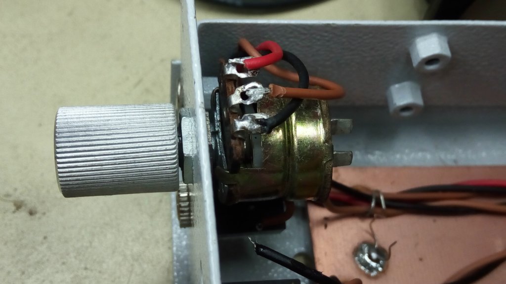
Connect the tuning pot


- Connect the 8-pin connector to the top side of the Raduino
- Solder the violet (left most) wire of the 8-pin connector to the middle of the tuning control
- Solder the green (3rd from the left) wire of the 8-pin connector to the left of the tuning control
- Solder the yellow (4th from the left) wire of the 8-pin connector to the right of the tuning control
- Solder the 0.1uF disc ceramic (marked as 104) between the yellow and violet wires on the tuning pot
Connect to the DDS connector of the BITX 
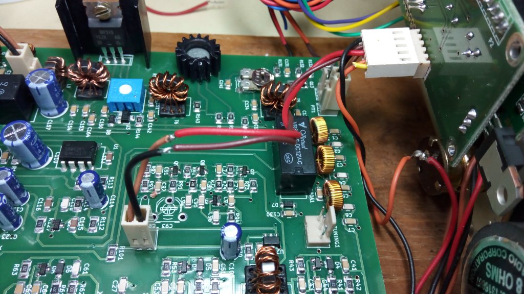
- Connect the 5-pin connector to the bottom side of the Raduino
- Solder the black wire to the DC power socket
- Solder the orange wire to the DC power switch on the volume control
- Connect a 2-pin connector to the DDS poin on the BITX board
- Solder the brown wire of the Raduino’s 5 pin connector to the black wire of the BITX’s DDS connector
- Solder the red wire of the Raduino’s 5 pin connector to the brown wire of the BITX’s DDS connector
The brown wire of the Raduino’s 5 pin connector does NOT connect to the brown wire of the BITX’s DDS conenctor!
Step 4: Volume Control
- Connect a 3-pin connector to the volume connector on the board

- Solder the red wire of the 3-pin connector to left lug of the volume control
- Solder the brown wire of the 3-pin connector to the middle lug of the volume control
- Solder the black wire of the 3-pin connector to the right lug of of the volume control

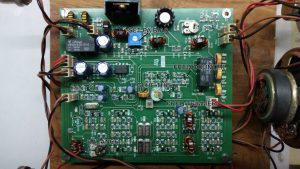
Step 5: Speaker
- Connect a 2-pin connector to the speaker connector on the board
- Solder the two ends to the speaker lugs on
- Use only an 8-ohms speaker or earphones. Lower impedance speaker may result in howling sound from audio oscillations
Step 6: Wiring up the microphone and Push to Talk
- Use a 2-pin wire connector for the mic.

- There are two solder pads behind the electret mic. The solder pad with small tracks to the case is connected to the ground (black) wire from the mic connector.

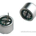
- The brown wire from the mic connector goes to the other solder pad on the mic
- Use another 2-pin wire connector for the the Push-To-Transmit connection. You may use the supplied push button switch to control transmit/receive.

Note:
Don’t solder the ground (black) wire of the speaker to the ground. It should only connect to the speaker or the earphone jack.
You may optionaly route the audio through the supplied stereo earphone jack to the speaker such that if you plug in the earphones/headset the speaker will disconnect. This is left as an exercise to you.
Step 8: Operate!
Always use the BITX40 with a properly tuned antenna or a dummy load.
- Insert an amp meter capable of measuring upto 5 amps into transceiver’s DC power line
- Switch on the transceiver. There should be a soft hiss from the speaker. The transceiver should draw 150-140 mA in receive mode
- Connect the antenna, loud band noise should be audible
- Tune around, listen to the sweet sound of an all analog receiver!
- Push the PTT and the current should now be between 300-350 mA
- Say ‘HAAAALOOO’ and the current should jump to 1 Amp
Are you still reading? Go and work some DX!
Alignment of the BITX40
The BITX40 comes pre-aligned out of the box. However, it may go out of alignment for some reason and here are the steps to align it. Keep the circuit handy while you do it. If you can’t understand what it means to ‘insert the ammeter into the power line’ ask someone for help.

- Attach a dummy load to the antenna
- Insert a ammeter (you may use your VOM meter in high amps range) into the PA power supply’s positive line
- Keep the PA BIAS preset (RV1) to fully clockwise position. Now when you press the PTT button, the ammeter should read about zero.
- Increase PA BIAS without speaking into the mic until the PA current shows 100 ma
- Give a loud and long HAAAALLLOOWW into the mic and the current should jump to slightly over 1 amp
- Adjust the RV136 to increase the PA drive if the current doesn’t jump all the way to 1A
- Keep monitoring your signal on a nearby receiver.
<>Note: You may use the RV136 to reduce the output power to drive an external linear or go QRPp.
Calibrating the Raduino
Due to variations in the frequency of the crystals used, the frequencies generated by the Raduino may be off by a few hundred hertz. You can easily calibrate like this :
- Attach a switch between the RED wire of the the 8-pin Raduino connector and the ground.
- Tune in an SSB signal of a known frequency. For instance, you can ask your friend to transmit on 7100.0 KHz
- Set the tuning pot such that it reads the actual frequency of the signal (ex: 7100 KHz). At this time the signal may not sound proper
- Now short the RED wire of the Raduino to ground. This puts the Raduino into calibration mode.
- Now carefully tune the signal to sound best
- Remove the RED wire’s short to save the calibration
Be sure to keep the RED wire from shorting to the ground again unless you want to recalibrate the Raduino.